
ECTphan™ 360
The ECTphan™ Phantom is a cylindrical, liquid filled container with a variety of tests for quality monitoring of single photon emission tomography (SPECT) systems.
The phantom can be used to evaluate the following SPECT system parameters: reconstructed uniformity, spatial resolution, low contrast resolution, pixel size, slice width, and center of rotation (COR). Additionally, the ECTphan™ Phantom data is suited for computer based analysis for the system parameters listed above.
For detailed information please refer to the ECTphan™ Manual.
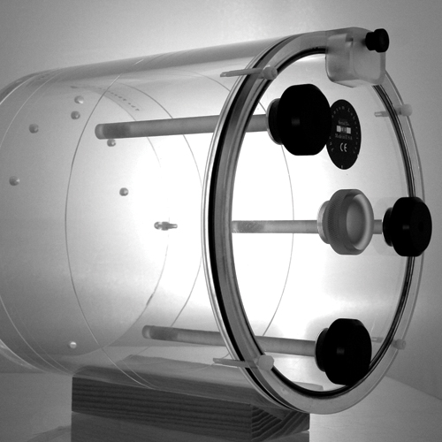
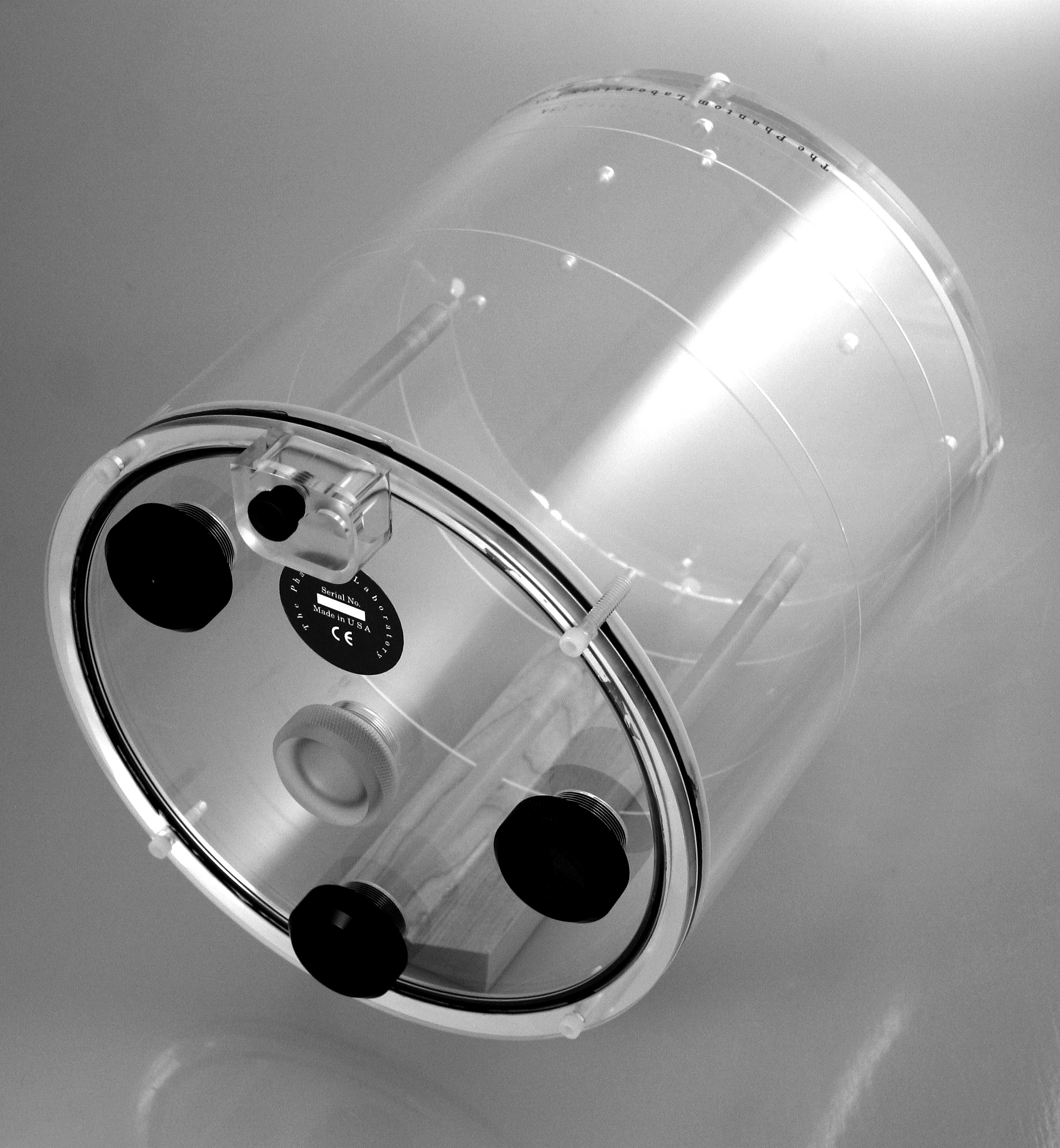
Configurations: The phantom lends itself to a number of user configurations The phantom has an end plate with 4 threaded holes (one in the center and three in a radial pattern) that can be filled with fillable ‘hot’ or ‘cold’ solid low contrast inserts. The contrast inserts can be replaced by plugs when not needed or to increase the uniformity area. A point source holder can be positioned at the phantom center for measurements of PSF, MTF and center of rotation. The test plate can also be removed easily to create a larger uniformity area.
Test-Summary
The ECTphan™ phantom consists of three main test areas: the test plate, a uniformity area and the end plate for inserts.
Test Plate
- Pixel Size
- Slice Width
- Spatial ResolutionUniformity Section
- Integral Uniformity
- Noise StatisticsEnd Plate
- Low Contrast Measurements (‘Hot’ or ‘Cold’)
- PSF
- MTF
- Center of Rotation.
Phantom Components
Test Plate: The test plate has 4 ‘hot’ holes spaced 120mm apart for measuring pixel size in X and Y axes. Four bar patterns up to 2.5lp/cm are available for visual evaluation of spatial resolution. Two opposed angled ramps provide the ability to measure slice thickness.
Uniformity Section: The uniformity section provides a 20cm diameter area that can be visually examined for artifacts and non-uniformities. The integral non-uniformity and RMS noise statistics can be calculated from the pixel values in the area.
End Plate: The end plate has threaded holes to mount the point source holder and the ‘hot’ and ‘cold’ low contrast inserts. When tests are not needed the holes may be plugged with SMR 168 plugs.
The point source holder can be positioned and imaged at the phantom center. The holder is designed for imaging the point sources in air and with scatter. From the reconstructed point source data, a point spread function (PSF) is generated and the full width at half maximum (FWHM) and full width at tenth maximum (FWTM) values can be measured. The modulation transfer function (MTF) may be generated from the PSF if software is available.
The external point source insert can be used to evaluate tilt of the camera heads. This is done by visual inspection of a rotating cine of the point source projection data and noting any significant change in the y-axis position of the point source.
The reconstructed point source data can also be used to demonstrate errors in the center of rotation (COR). Items to note on the reconstructed data are point source width in three dimensions, shape, and indications of streaking or other artifacts.
The ECTphan™ Phantom is supplied with either 3 solid or 3 hollow low contrast inserts. These inserts can be threaded into the phantom end plate in a radial pattern 75mm off the center axis, or one can be placed in the phantom’s central axis. The inserts are comprised of three sections: 10, 15, and 20mm in diameter and 40mm long.
The hollow inserts are filled through a port at the threaded end. The hollow inserts are used to simulate “hot” lesions. The solid inserts are used to simulate “cold” lesions.
Note: ECTphan™ phantoms are not supplied with contrast fill solutions. Customers are required to add their own fill solutions.