
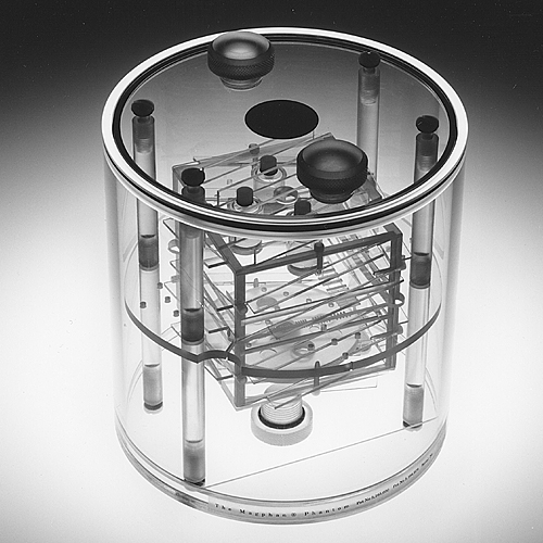
Cylindrical Magphan® 170
Magphan® phantoms are designed to perform a wide range of performance evaluations of Magnetic Resonance Imaging (MRI) Scanners.
The Magphan® SMR170 phantom was developed in the 1990s, in the early days of MRI. Our newer EMR and TMR Magphan® phantoms are designed for modern MRI scanners, and we highly recommend them over the SMR170. We can, however, manufacture the 170 phantom for customers who request them.
The Magphan® SMR170 has a conventional cylindrical housing for test groups and manufacturers who base their performance specifications on cylindrical phantoms. It has a removable end plate for internal access. The acrylic cylinder has an outer diameter of 20cm and an inner diameter of 19cm. The Magphan® SMR170 phantoms are shipped without any fluid. Customers must fill them with appropriate MR solutions.
For detailed information please refer to the Magphan® SMR170 Manual.
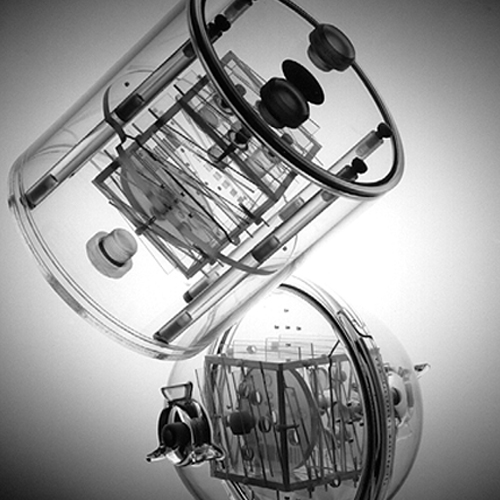
Test Cube: Both the cylindrical and spherical Magphan® use a 10cm test cube for image quality measurements. Manufactured from 6mm-thick polycarbonate plastic the test cube has an outer diameter of 10cm. The test cube contains the slice thickness ramps, sensitometry vials, a high-resolution test plate, and a low contrast disk.
Configurations: The test cube plates can be assembled in the standard 2-D configuration, with dual opposed slice thickness ramps which allow operators to rapidly verify that the phantom’s z axis is precisely aligned perpendicular to the imaging plane. Nylon screws hold the unit together, allowing you to change test plates or cube sides into a 3-dimensional configuration. The 3-D configuration allows x, y, and z slice geometry measurements to be obtained from a single data acquisition
Test-Summary
The test cube and phantom housing contain features that allow for comprehensive testing of the maximum achievable critical MRI scanner parameters. The major components and the tests they support are listed below.
Slice Thickness Ramps
- Phantom Position
- Scan Slice Width
- Multi-slice Spacing and Contiguity
- Patient Alignment (3D)
- Table Increment AccuracySensitometry Vials
- T1 Measurements
- T2 MeasurementsHigh Resolution Test Plate
- High Resolution Measurements (1 to 11 line pairs per cm)
- Geometric DistortionCube Support Disk
- Geometric Distortion
- Pixel(matrix) size verification.Outer Housing
- Spatial Uniformity
- Signal to Noise Ratio
Phantom Components
Slice Thickness Ramps: The slice thickness ramps are mounted on the exterior of the test cube. The ramps, which are 2mm thick and 10mm wide, are placed at a shallow 14° angle to the phantom’s axes, providing a magnification factor of 4x for slice width measurements. Opposed ramps cross at the center of the cube’s test planes for alignment verification.The ramps can be used to test the indexing between slices within a multislice sequence and for testing table increment accuracy.
Sensitometry Vials: The sensitometry samples are stored in four cylindrical vials with an outer diameter of 1.9cm and an inner diameter of 1.6cm. The vials can be filled with a variety of solutions through 0.6cm (1/4 inch) ports on the outside of the cube for T1 and T2 measurements.
High Resolution Test Plate: A high resolution gauge is cut into a 2mm-thick acrylic plate that is supported by channels inside the Test Cube. The high-resolution test is performed by using a series of rectangular slots that form a test pattern which ranges from one to eleven line pairs per cm (5mm to 0.45mm resolution). The slots for testing between one and four line pairs per cm are 1.25cm long, and 0.9cm long for tests involving between five and eleven line pairs per cm.
To test for geometric distortion (spatial linearity), 3mm holes are spaced in square patterns of 2cm, 4cm, and 8cm. The system’s geometric distortion can be evaluated by measuring the distance between these holes.
Low Contrast Disk: Low contrast sensitivity is performed with an acrylic disk mounted on the base of the test cube. Circular recesses in the disk generate low contrast images through volume averaging. The four sets of three circular recesses are 0.5mm, 0.75mm, 1.0mm, and 2.0mm deep, with diameters of 4mm, 6mm, and 10mm.
Cube Support Disk: The two-piece cube support disk holds the cube inside the phantom housing and can be easily installed and removed. Along with fixing the test cube’s position, the support disk provides information for spatial linearity measurements.
Geometric distortion is tested by measuring the diameter of the Magphan® in the x and y directions. Geometric distortion can also be evaluated by measuring the distance between the 3mm holes that are configured into 8cm, 10cm and 12cm squares in the support disk.
Outer Housing: The housing components consist of an outer housing and a cube support disk (which supports the 10cm test cube). Comprehensive spatial uniformity measurements can be made using the phantom housing with the test cube and support disk removed. The housings are easy to clean and allow the use of gels as well as liquid solutions. Multiple ports allow unrestricted flow when draining.
Note: Magphan® phantoms are not supplied with contrast fill solutions. Customers are required to add their own fill solutions.