
Catphan® 700
The Catphan® 700 is intended for use with state of the art CT scanners and research that require an advanced phantom to measure their full potential.
The phantom retains many of the tests and features offered in the other Catphan® models including the CTP515 Low Contrast Module and integrated case mounting system. Other test objects have been refined in this development including the addition of test patterns up to 30 lp/cm in the new CTP714 High Resolution Module, the addition of smaller acrylic spheres to our low contrast sphere array contained in the CTP682 sensitometry slice geometry module, and additional bone and lung samples to assist customers using their CT images for radiation therapy treatment planning. The Cathan® 700 also contains the new CTP758 wave insert for measuring slice geometry and resolution across the scan area.
Also, in order to address possible variables due to test pattern orientation with the scanners x and y axis, the phantom has a new rotation mount. This enables the mounted phantom to be rotated 360° with alignment detents at 45° intervals to study possible angular position-dependent results.
Smári Image Analysis Service
The Catphan® 700 is equipped with Smári, a powerful, web-based image analysis service created by The Phantom Laboratory. Smári delivers automated phantom image analysis in the cloud and maintains measurements in a database for trend analysis, machine comparisons, and historical records.
For detailed phantom information please refer to the Catphan® 700 Product Guide and Data Sheet.
Test-Summary
CTP682
- sensitometry (linearity)
- scan slice geometry
- slice sensitivity profile
- slice width with both wire and bead ramps
- pixel (matrix) size
- circular symmetry
- phantom position verification
- patient alignment system check
- scan incrementation
- MTF using both wire or bead point source
- Contrast targets using volume averaged spheresCTP714
- high resolution measurement - up to 30 line pairs per cmCTP515
- low contrast sensitivity
- comparative subslice and supra-slice low contrast sensitivityCTP758, CTP723
- harmonics and intensity profile from wave insertCTP712
- spatial uniformity
- noise (precision)
Modules
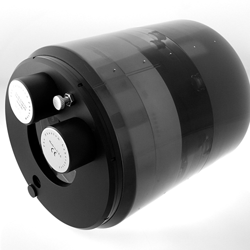
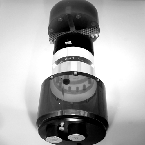
The Catphan® 700 consists of 6 modules enclosed in a 20cm housing.
CTP682 Slice Geometry and Sensitometry Module: The CTP682 module contains three sets of opposed slice geometry ramps. Opposed 23 degree ramps are used to measure scan slice geometry, verify phantom position and check the patient alignment system and the scanner table incrementation. The shallow 23 degree angle allows for more precise measurement of slice thickness than the commonly used 45 degree ramps. The coarse ramp with a z-axis height of 38mm uses 0.28mm beads set in 1mm z-axis increments and the fine ramps use 0.18mm beads set at .25mm z-axis increments. One of the ramp sets uses 0.15mm thin wires to allow for accurate measurement of thin 1 and 2mm slices without streaking artifacts. Gantry angle (up to 10 degrees) can be determined by the ratio of the ramp lengths thus avoiding erroneous measurements.
The module includes 10 sensitometry targets (Acrylic, Bone-50%, LDPE, Bone-20%, Teflon, polystyrene, Delrin™, Lung Foam #7112, PMP and air, and a small vial for water) to measure CT number linearity. The increased number of targets makes this module suitable for radiotherapy CT sensitometry.
The module also contains eight acrylic spheres to evaluate the scanner’s imaging of subslice spherical volumes. The sphere diameters are 1, 1.5, 2, 3, 4, 6, 8, and 10mm.
Pixel size can be determined by counting the pixels between the centers of diametrically opposed sensitometry targets.
CTP714 High Resolution Module: The unique design of the CTP714 minimizes visual artifacts by reducing the amount of high contrast material. The 2mm thick aluminum contrast figures are cast into position on the radial octagonal pattern, which has resolution sections ranging from 1 to 30 line pairs per cm. This resolution gauge pattern greatly reduces the possibility of streaking artifacts from other test objects. The combination of the octagonal design and the rotating mount with 45° indices enables all gauge segments to be measured either aligned with the x or y axis, or at a 45°or 90° angle.
CTP515 Low Contrast Module: The CTP515 consists of a series of cylindrical rods of various diameters and three contrast levels to measure low contrast performance. The 40mm-long rods provide consistent contrast values at all z-axis positions, thereby avoiding any volume-averaging errors as you scan through the section. The unique subslice test objects enable evaluation of the effectiveness of different scan protocols (pitch, slice width and reconstruction algorithms) in resolving subslice low contrast objects.
For selection of helical and multi-slice image protocols, unique subslice low contrast targets (truncated cylinders) have been included in this module. Comparing the images obtained by scanning the subslice targets with different imaging settings (slice width, pitch and reconstruction algorithms) provides valuable information to assist with the selection of optimal protocols for identifying small low contrast objects such as tumors.
All of the various samples and the background material have equivalent effective atomic numbers; only the density is varied to produce changes in the effective attenuation coefficients.
Subslice targets have a nominal 1.0% contrast and z-axis lengths of 3, 5, and 7mm. For each of these lengths, there are targets with diameters of 3, 5, 7 and 9mm.
CTP758 Wave Insert: The wave ramp is designed to look at the slice geometry across the phantom as impacted by both in-plane resolution and z-axis (slice thickness) resolution. This is achieved by offering a periodic pattern that is angled through the z-axis at a given ramp angle. By analyzing a profile through the two ramps, information on the 3D voxel resolution is revealed.
A perfect CT image (with no loss of resolution) of the test object would produce a consistent geometric pattern of the intersection of a line with the pair of angled ramps. As the waveform deviates away from its ideal form due to the finite resolution of the scanner in all dimensions (slice thickness and in-plane resolution), noise effects and other sources of non-uniformity can be measured and analyzed to determine and evaluate imaging performance of the tomographic imaging device. Spatial performance includes the device’s ability to accurately image an object, including in-plane resolution characteristics, slice thickness, angular orientation of the slice plane, and uniformity of response across the scan field. If, for instance, there is a variation in slice thickness throughout the slice, or from one side of the slice to another, or if the mean of the profile is changing, due to non-uniformity of the scanner, these variations will be reflected in the image of the test object, and the waveform profiles taken across the angled ramps in the image will encode these properties.
For a detailed look at the imaging physics behind the Wave module see Dr. David Goodenough et al. ,2016
CTP723 Bead Blocks: Six point sources are also offered in the phantom to provide simultaneous information on the in-plane PSF, and resulting MTF.
CTP712 Uniformity Module: The 20cm diameter image uniformity module is cast from a uniform material with a CT number designed to be within 2% (20H) of water’s density under standard scanning protocols. The typically recorded CT numbers range from 5H to 18H. This module is used for measurements of spatial uniformity, mean CT number and noise value.
Use of a solid material eliminates leaking or risk of damage from exposure to freezing temperatures. The CTP712 solid-image uniformity module provides consistent results, is much more convenient to use than modules using water-filled tanks, and eliminates variations due to different water sources. This solid material’s high radial and axial uniformity makes it an ideal substitute for water. It has been thoroughly tested over a wide variety of variables in the x, y and z planes and has proven stable in all applications.